
Views: 0 Author: Site Editor Publish Time: 2026-10-16 Origin: Site


Selecting the correct water pump determines whether your fluid transfer system runs continuously or fails prematurely. Deploying the wrong pump architecture leads to system breakdowns, severe cavitation, and excessive downtime on the job site. Buyers face a fragmented market split between dynamic and positive displacement mechanics. You must balance flow rates, pressure requirements, fluid viscosity, and power configurations against long-term operational demands. This guide breaks down the primary classifications of fluid transfer equipment, specialized industrial applications, and the technical evaluation frameworks you need. We will cover how to match pump mechanics to specific operational demands, ensuring you specify the right hardware for construction dewatering, chemical dosing, or heavy equipment integration. You will learn exactly how to evaluate head pressure, avoid dry running, and select materials that survive harsh field conditions.
Classification Dictates Application: All water pumps fall into two primary categories—dynamic (centrifugal) for high-flow/low-viscosity needs, and positive displacement for high-pressure/variable-viscosity applications.
System Architecture Matters: Evaluating Total Dynamic Head (TDH) and Net Positive Suction Head (NPSH) is non-negotiable to prevent cavitation and ensure operational efficiency.
Specialized Integration: Heavy-duty applications require purpose-built solutions, such as an Electric Diaphragm Water Pump for chemical metering or a Road Roller Water Pump for construction dust suppression.
Risk Mitigation: Proper material selection and preventative maintenance protocols for mechanical seals and bearings drastically reduce lifecycle costs.
Every pumping system relies on basic physics to move fluid from a low-energy state to a high-energy state. Engineers divide these systems into two distinct families based on how they transfer energy to the liquid. Understanding this mechanical divide helps you specify equipment that survives continuous industrial operation. If you put a dynamic pump in a high-viscosity application, it will stall. If you put a positive displacement pump in a high-volume flood control scenario, it will bottleneck the entire operation.
Dynamic pumps use rotational kinetic energy. A rotating impeller sits inside a stationary casing called a volute. Fluid enters the center of the impeller, and the spinning vanes accelerate the liquid outward. The volute captures this high-velocity fluid and gradually expands in area. This expansion forces the fluid to slow down, converting kinetic energy into static pressure. Centrifugal designs handle continuous, high-volume transfer of thin, non-viscous fluids like clean water. They have simple construction and minimal moving parts. You get a smooth, non-pulsating flow. We use these extensively in municipal water lines and cooling towers because they run for years with basic bearing lubrication.
Positive displacement mechanics work differently. Instead of using velocity, these pumps trap a fixed volume of fluid inside a mechanical cavity. Moving parts then physically push that trapped volume through the discharge pipe. Because they move an exact amount of fluid with every stroke or rotation, they generate massive pressure. They handle highly viscous fluids, shear-sensitive chemicals, and applications needing precise flow control. System backpressure does not affect their output. If you need to push thick sludge through a hundred feet of pipe, you use positive displacement.
The operational differences dictate where you install them. In a centrifugal system, the flow rate drops heavily as system pressure rises. If you close a discharge valve on a centrifugal pump, the fluid just churns inside the casing, eventually heating up. Conversely, a positive displacement pump keeps pushing the same volume regardless of pressure spikes. Closing a discharge valve on a positive displacement unit causes pressure to spike instantly. The motor will stall, a pipe will burst, or a mechanical relief valve will blow open. You must install pressure relief valves on all positive displacement discharge lines to prevent catastrophic blowouts.
Radial flow pumps are the most common centrifugal design on job sites. Fluid enters parallel to the pump shaft and discharges at a strict 90-degree angle. This sharp redirection creates heavy centrifugal force. We use radial pumps for high-pressure and high-head applications, like pushing water up a multi-story building. Axial flow pumps operate like boat propellers. Fluid enters and exits parallel to the shaft without changing direction. This straight-through design generates very little pressure but moves massive volumes of water. We rely on axial pumps for flood control, agricultural irrigation, and draining large retention ponds quickly.
End-suction pumps use a single-stage design where fluid enters the impeller directly through the front of the casing. The motor and pump shaft sit horizontally. These are the standard workhorses for commercial HVAC cooling towers, municipal water supply networks, and general fluid transfer. Inline pumps function similarly but have suction and discharge nozzles positioned in a straight line. Installers mount the pump directly into the piping network without pouring a separate concrete baseplate. This saves valuable mechanical room floor space and reduces installation labor.
Submersible pumps use a hermetically sealed motor close-coupled to the pump body. The entire assembly drops completely underwater. This design eliminates priming issues and prevents motor cavitation in deep well extraction. Immersible pumps differ slightly. The pump end sits submerged in the fluid, but a long vertical shaft connects it to a dry motor mounted safely above the liquid level. Sump pumps often use this vertical immersible design to drain collection pits and basements. Keeping the electrical components above the moisture line prevents short circuits and extends motor life.
Handling raw waste requires specialized centrifugal engineering. Standard impellers clog instantly when they hit sanitary solids and fibrous materials. Sewage pumps feature recessed, vortex, or single-channel impellers. These create a whirlpool effect, allowing solids to pass through the casing without snagging on the vanes. Heavy-duty variants incorporate hardened steel grinder or macerator mechanisms at the suction inlet. These blades shred debris into a fine slurry before it enters the impeller. This prevents downstream pipe blockages and keeps municipal lift stations operational.
Jet pumps sit above ground and use the venturi effect to draw water from shallow depths. They push a small stream of water through a narrow nozzle, creating a low-pressure vacuum that pulls additional water up from the well. Shallow well jet pumps are limited by atmospheric pressure. They only lift water from depths of roughly 25 feet. For deeper water tables, we specify deep well submersible configurations. Crews lower these units directly into the well casing. They push water up to the surface rather than relying on suction lift, making them far more efficient for deep extraction.
When an application demands extreme discharge pressure, a single impeller fails to deliver. Multistage pumps stack multiple impellers in series along a single shaft. Fluid exits the first impeller and feeds directly into the eye of the second. This compounds the pressure at each stage. You get massive head pressure without needing an oversized motor footprint. Split-case pumps feature a casing divided horizontally or vertically. Maintenance teams can unbolt the top half to inspect and replace internal rotating assemblies. They do this without disconnecting the heavy suction and discharge piping, cutting downtime in half.
Commercial plumbing loops and hydronic heating systems rely on hot water recirculating pumps. These are low-flow, continuous-duty centrifugal units. They keep hot water moving slowly through the pipes, ensuring instant hot water at any fixture. This eliminates the waste of running cold water down the drain while waiting for the tap to heat up. Manufacturers build them with specialized bronze or stainless steel to resist the corrosive effects of oxygenated hot water. Many use magnetic drive technology to eliminate mechanical seal leaks entirely.
Rotary pumps use rotating mechanical components to create a void. This draws fluid in and sweeps it toward the discharge port. Gear pumps use interlocking metal gears. As the teeth separate on the suction side, they pull fluid in. As they mesh on the discharge side, they force fluid out. Lobe pumps operate similarly but use rounded lobes that do not touch. This makes them ideal for shear-sensitive food processing where you cannot crush the product. Vane pumps feature sliding blades mounted on an eccentric rotor. The blades adjust automatically for wear, making them highly effective for handling thin solvents and fuels.
Reciprocating pumps rely on a back-and-forth motion. A piston or plunger retracts within a cylinder, opening an inlet valve and drawing fluid in. The stroke then reverses, closing the inlet, opening the discharge valve, and expelling the fluid under immense mechanical force. These pumps dominate ultra-high-pressure applications. You find them powering industrial pressure washers, reverse osmosis desalination plants, and heavy-duty surface cleaning equipment. They require heavy dampeners on the discharge line to smooth out the intense pulsation caused by the reciprocating strokes.
Linear mechanics represent a more specialized subset of positive displacement technology. Rope pumps and chain pumps use a continuous loop fitted with washers or discs pulled through a pipe. As the discs move upward, they trap water and lift it to the surface. While rarely used in high-tech manufacturing, linear displacement pumps remain highly effective in agricultural settings and low-tech rural water extraction. They excel in specific industrial lifting applications where simplicity and field repairability matter more than raw efficiency.
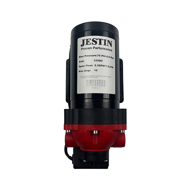
An Electric Diaphragm Water Pump operates using a flexible membrane. An electric motor drives a connecting rod that pushes and pulls the diaphragm. This flexing motion creates a vacuum to draw fluid in and pressure to push it out. Because the fluid remains entirely contained within the diaphragm chamber, there are no dynamic seals to leak or wear out. They run dry indefinitely without damage and are inherently self-priming.
These characteristics make them exceptional dosing pumps. Water treatment facilities and chemical manufacturing plants rely on them for precise, repeatable chemical metering. Operators adjust the stroke length or motor speed to inject exact volumes of chlorine, acids, or flocculants into a process stream safely and accurately.
Standard commercial pumps fail rapidly in construction environments. Mobile heavy equipment requires pumps engineered to survive extreme vibration, chassis twisting, and exposure to abrasive dust. Mounting brackets must use heavy-duty rubber isolation dampers. Housings are often cast from ductile iron or reinforced polymers to resist impact damage from flying rocks. Furthermore, these pumps must operate on direct current (12V or 24V) to integrate seamlessly with the vehicle's electrical architecture. You cannot run standard AC pumps on a diesel excavator without complex inverters.
Compaction equipment relies heavily on specialized fluid management. A Road Roller Water Pump must deliver consistent, low-volume flow across the entire width of the machine. These pumps are typically compact, vibration-resistant diaphragm or small centrifugal units. They must maintain reliable suction from onboard water tanks, even as the equipment operates on steep inclines or uneven terrain. Failure of this pump halts paving operations immediately. If the drum runs dry, asphalt sticks to the steel, ruining the mat finish. Rugged reliability is the primary procurement metric for these components.
The pump serves as the heart of the Road Roller Water Spray System. This system mists water onto the steel compaction drums to prevent hot asphalt from sticking to the metal surface. On soil compactors, the system provides necessary dust suppression to meet environmental regulations. Because construction site water is rarely clean, the system requires robust inline filtration to capture rust, sand, and debris. This filtration protects the delicate spray nozzles from clogging. Clean nozzles ensure an even spray pattern across the drum, preventing dry spots and asphalt tearing.
Construction site dewatering demands pumps capable of moving mud, rocks, and debris. Trash pumps are specialized centrifugal units featuring deep, wide volutes and open impellers. They pass large spherical solids without jamming. Utility pumps serve a similar function for cleaner water, quickly draining flooded trenches or utility vaults. Both designs prioritize portability. They feature steel roll cages, heavy-duty lifting eyes, and quick-disconnect cam-lock hose fittings. This allows crews to deploy them rapidly during flash floods or unexpected trench water intrusion.
Alternating current (AC) electric motors represent the industry standard for fixed installations. They offer quiet, emission-free operation and require minimal maintenance compared to internal combustion engines. They integrate easily with Variable Frequency Drives (VFDs) for precise flow control and energy optimization. However, their reliance on grid access limits their mobility. In remote locations, powering large electric pumps requires towing heavy, expensive diesel generators to the site.
Internal combustion engines provide total operational independence. Gas and diesel-powered pumps are essential for remote agricultural irrigation, emergency flood dewatering, and mobile construction sites. Diesel engines deliver massive torque, allowing them to drive large trash pumps through thick sludge. The trade-offs include significant noise pollution, hazardous exhaust emissions, and a heavy maintenance burden. Crews must perform regular oil changes, filter replacements, and strict fuel management to prevent stale diesel from clogging the injectors.
Field operators must follow strict pre-start checks for diesel-driven units:
Check engine oil and coolant levels before engaging the starter.
Drain water separators in the fuel line to protect injectors.
Inspect the drive coupling between the engine and pump end for torn rubber inserts.
Verify the discharge valve is partially open to prevent dead-heading the pump on startup.
Niche applications demand alternative power delivery. Solar-powered pumps use photovoltaic arrays to drive highly efficient DC motors. They are increasingly popular for livestock watering and remote well extraction where grid power is unavailable and hauling fuel is impractical. Pneumatic pumps operate on compressed air rather than electricity. Air-operated double diaphragm (AODD) pumps are the standard in explosive environments or chemical plants. The absence of electrical components completely eliminates the risk of sparks, making them intrinsically safe for pumping volatile solvents.
Proper pump selection requires precise hydraulic calculations. Flow rate, measured in Gallons Per Minute (GPM), dictates the volume of fluid moved. Total Dynamic Head (TDH) measures the total resistance the pump must overcome. Engineers plot the required GPM and TDH against a manufacturer's pump performance curve. This ensures the pump operates at its Best Efficiency Point (BEP), preventing premature bearing wear.
To calculate your exact TDH, follow these field measurements:
Measure the static suction lift from the water level to the pump eye.
Measure the static discharge head from the pump eye to the final discharge point.
Calculate friction loss for the entire length of pipe using a standard friction loss chart.
Add the friction loss of all elbows, valves, and fittings in the system.
Sum these values to determine the total resistance the pump must overcome.
Water is rarely just water in industrial settings. Fluid properties dictate mechanical design. Specific gravity measures the fluid's density compared to pure water. Heavier fluids require larger motors to prevent stalling. Kinematic viscosity measures flow resistance. Highly viscous fluids destroy centrifugal efficiency and mandate positive displacement mechanics. Furthermore, suspended solids dictate impeller selection. Clean water allows for highly efficient closed impellers. Debris-laden fluid requires open impellers or grinder mechanisms to prevent catastrophic clogging.
Chemical compatibility between the fluid and the wetted pump components is critical for longevity. Selecting the wrong material leads to rapid corrosion, abrasive wear, and structural failure.
Material | Primary Characteristics | Ideal Applications |
|---|---|---|
Cast Iron | High strength, excellent abrasion resistance, susceptible to rust. | Standard municipal water, sewage, heavy construction dewatering. |
Stainless Steel (316) | Superior corrosion resistance, handles temperature extremes well. | Food processing, reverse osmosis, mild chemical transfer. |
Bronze | Resists galvanic corrosion, does not spark, handles oxygenated water. | Marine environments, hot water recirculation, HVAC loops. |
PTFE / Polypropylene | Exceptional chemical inertness, lightweight, lower pressure limits. | Aggressive acids, highly corrosive dosing, semiconductor manufacturing. |
Cavitation destroys impellers faster than any abrasive fluid. It occurs when the pressure at the pump inlet drops below the fluid's vapor pressure, causing the liquid to boil instantly. These vapor bubbles travel into the high-pressure zone of the impeller and collapse with explosive force. This collapse pits the metal and shatters bearings. Preventing cavitation requires managing Net Positive Suction Head (NPSH). The system's available suction pressure (NPSHa) must always exceed the pump's required suction pressure (NPSHr) by a safe margin.
The point where the rotating shaft enters the stationary casing is the most vulnerable part of any pump. Traditional packing glands require a controlled, continuous drip of fluid to remain lubricated. This is unacceptable for hazardous chemicals. Mechanical seals use highly polished faces pressed together by springs to prevent leakage. However, these faces are fragile. Abrasive particles or sudden temperature shocks will crack them. For zero-leakage requirements, operators must transition to sealless magnetic drive or diaphragm architectures.
Operating a pump without fluid is disastrous. In centrifugal pumps, the fluid acts as a necessary coolant and lubricant for the mechanical seals. Running dry for even a few minutes causes extreme heat buildup, shattering seal faces and melting plastic impellers. Positive displacement pumps operating dry will rapidly destroy their stators or gears. Protecting the asset requires automated control systems. Installers must integrate float switches in the suction tank, flow meters in the discharge line, or motor current monitors to shut down the system instantly if fluid flow ceases.
Field maintenance dictates the lifespan of your pumping equipment. Follow these steps to keep systems operational:
Inspect mechanical seals weekly for weeping or crust buildup.
Grease motor bearings according to the manufacturer's exact hour-meter intervals.
Check alignment between the motor and pump shaft using a laser alignment tool to prevent vibration.
Clean suction strainers daily on construction sites to prevent flow restriction and cavitation.
Test pressure relief valves on positive displacement systems monthly to ensure they open at the correct setpoint.
Symptom | Potential Cause | Field Action Required |
|---|---|---|
Excessive Vibration | Misalignment or bearing failure. | Check shaft alignment with a laser tool; replace worn bearings immediately. |
Loud "Marbles" Sound | Cavitation due to low suction pressure. | Clean suction strainer; increase suction pipe diameter; lower pump elevation. |
Zero Flow on Startup | Loss of prime or air leak in suction line. | Re-prime the casing; pressure test suction piping for pinhole leaks. |
Motor Tripping Breaker | Specific gravity too high or impeller jammed. | Verify fluid density matches motor rating; inspect volute for debris. |
Calculate your exact Total Dynamic Head (TDH) and required flow rate (GPM) before opening any manufacturer catalogs.
Match the specific gravity, viscosity, and chemical aggressiveness of your fluid to the correct pump housing and elastomer materials.
Install automated dry-run protection, such as float switches or current monitors, to safeguard mechanical seals and rotating assemblies.
Verify your Net Positive Suction Head Available (NPSHa) exceeds the pump's requirements to eliminate cavitation risks.
A: Centrifugal pumps use a spinning impeller to convert fluid velocity into pressure. Their flow rate drops as system pressure rises. Positive displacement pumps trap a fixed volume of fluid and mechanically force it out. They maintain a constant flow rate regardless of pressure changes, making them ideal for high-pressure or viscous applications.
A: Calculate your Total Dynamic Head (TDH), which includes elevation changes and pipe friction loss. Determine your required flow rate in Gallons Per Minute (GPM). Plot these two metrics against a manufacturer's pump performance curve to ensure the pump operates efficiently without overloading the motor.
A: No. Standard centrifugal pumps lose efficiency rapidly with viscous fluids and use materials that degrade under chemical attack. You must specify positive displacement designs, such as gear or diaphragm pumps, constructed from chemically inert materials like PTFE or stainless steel to handle aggressive or thick fluids safely.
A: Cavitation occurs when the Net Positive Suction Head Available (NPSHa) is lower than the pump requires. This low pressure causes the water to boil into vapor bubbles. When these bubbles reach the high-pressure impeller zone, they collapse violently, causing severe pitting, vibration, and eventual mechanical failure.
A: These systems typically use specialized 12V or 24V electric diaphragm pumps or compact centrifugal units. They are engineered to withstand severe machine vibration and provide continuous, low-pressure misting to prevent hot asphalt from adhering to the steel compaction drums.
A: Yes. Because they use a flexing membrane to create a strong internal vacuum, they pull air out of the suction line and lift fluid from a lower elevation. They can also run dry indefinitely without damaging internal components, making them highly reliable for suction-lift applications.
A: Jet pumps are installed above ground and use a venturi nozzle to create a vacuum, pulling water up from shallow wells under 25 feet. Submersible pumps are installed deep underwater inside the well casing. They push fluid up to the surface, allowing them to operate efficiently at much greater depths.


